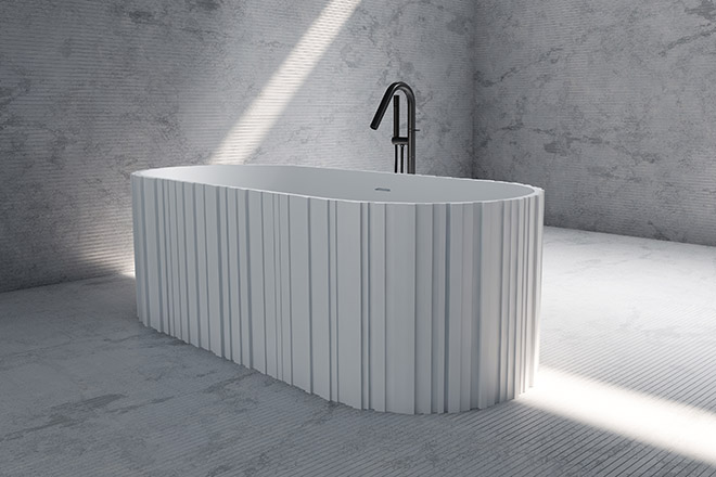
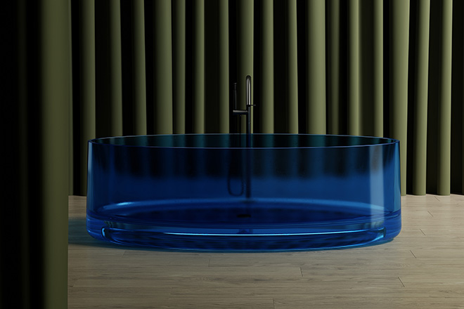
In any project where luxury and functionality intersect, it is essential to carefully plan how to install freestanding bath units. Proper installation goes beyond aesthetics, requiring early coordination between trades, attention to floor tolerances, drainage alignment, and finish protection. By defining responsibilities and following a structured approach, projects can achieve both the desired visual impact and reliable long-term performance of freestanding baths.
Definition, scope, and coordination responsibilities
A freestanding bath is typically specified as a finished, exposed fixture that is installed clear of adjacent walls, with all performance outcomes (level, drainage, watertightness, finish protection, and service access) dependent on early coordination between the bath supplier, plumbing contractor, waterproofing trade, and the general contractor. In project environments, the “freestanding” aesthetic does not reduce technical dependencies; it increases the need for accurate set-out because tolerance stack-up is visible at the floor interface, filler alignment, and drain positioning.
Freestanding bath typologies and mounting concepts (footed base, skirted base, integral plinth)
Freestanding bath tubs generally fall into three mounting concepts, each with different substrate and rough-in implications:
- Footed base (adjustable feet or fixed feet): Load is transferred through discrete bearing points. This simplifies leveling but increases sensitivity to point loading on floor finishes and to long-term movement over time if the substrate deflects.
- Skirted base (concealed feet under a continuous skirt): Load is distributed more evenly, but installers have less visual access to bearing points, making pre-verification of floor flatness and drain alignment more critical.
- Integral plinth/base frame: Common in solid-surface or engineered composite systems. These often require tighter floor flatness targets to avoid rocking and to maintain a consistent perimeter seal line.
Selection should be aligned with the project’s service strategy (access below vs. no access), floor build-up, and the plumbing rough-in approach (floor drain vs. wall outlet with concealed trap assemblies where permitted).
Responsibility matrix: plumbing rough-in, substrate readiness, waterproofing, and final commissioning
For procurement and project control, define responsibilities in the scope notes and method statements rather than assuming trade conventions. A typical responsibility allocation is:
- Plumbing contractor: drain line location, trap and vent compliance, supply line routing for tub filler, pressure testing, and final connection to the waste/overflow and filler system.
- Waterproofing trade: continuity of membranes at penetrations (floor-mounted filler, floor drain), compatible sealant interfaces, and curing sequencing around the tub footprint.
- Flooring/tile trade: substrate flatness/levelness within tolerance, finish protection until commissioning, and movement joint strategy at perimeters.
- General contractor / commissioning agent: access provisions (panels or ceiling access below), sign-off checklists, and evidence capture (photos of rough-in before concealment).
This matrix reduces coordination risk that often shows up late as rework around the drain hole location, filler anchorage conflicts, or compromised waterproofing continuity.
Submittal set requirements: cut sheets, CAD/BIM, rough-in drawings, and method statements
For repeatable freestanding tub installation across multi-unit projects, the submittal set should be treated as a system package, not a single cut sheet. Minimum documentation typically includes:
- Dimensioned product cut sheet (overall length/width/height, rim geometry, base footprint)
- Drain/overflow details (connection type, tailpiece length range, overflow elevation)
- Rough-in drawings (plan and section set-out, tolerances, required box-out sizes)
- CAD/BIM objects aligned to the supplied revision
- Approved method statement covering handling, finish protection, leveling approach, and commissioning tests
- Bill of materials for compatible drain kits, trap adapters, and filler options
How is floor loading verified for a filled freestanding bath?
Floor loading verification is normally addressed as a structural coordination item, not an installation afterthought. Verification should use the maximum filled weight (bath + water volume + occupant allowance) and apply it to the actual bearing configuration (feet vs. plinth). For footed bases, check point loads against the finished floor build-up and the structural deck; for plinth bases, check distributed load and deflection limits. In multi-storey construction, confirm that deflection under live load will not exceed finish or sealant tolerances, as minor movement over time can lead to perimeter seal fatigue or perceived rocking.
Pre-install planning constraints (layout, access, sequencing)
Freestanding baths are often positioned to achieve a design intent, but in project execution the governing constraints are access, rough-in feasibility, and finish sequencing. Planning should be finalized early enough to lock drain locations before slab pours or underfloor service closures.
Space planning: clearances for service, cleaning access, and adjacent fixture coordination
Professional layouts should account for:
- Service access: ability to reach the waste/overflow connections and trap for inspection and remedial work, either from below or via a planned access route.
- Cleaning access: a defined clearance around the tub for housekeeping equipment where hospitality or multi-family turnover is expected.
- Adjacent fixture coordination: clearances between freestanding tub, wall-mounted fillers, floor-mounted tub filler, screens, towel rails, and door swings—especially where a floor-mounted faucet requires a stable anchorage zone free of underfloor obstructions.
Where a “how to install a freestanding tub” query often assumes flexible positioning, project work requires fixed set-out coordinates and clash-free routing zones.
Underfloor access vs slab-on-grade planning (access panels, trenching, or box-outs)
Drain and supply routing is simplest when underfloor access is available (service ceiling below, raised floor, or accessible void). If not, planning typically requires one of the following:
- Slab trenching and patching to route the drain line and, if applicable, hot and cold water supplies for a floor-mounted tub filler.
- Pre-formed box-outs to keep the trap and connections within an accessible cavity prior to pour.
- Local access panels (where acceptable to the authority having jurisdiction and aligned to fire/acoustic requirements).
The procurement risk is highest when the bath is selected before confirming whether the building structure permits the required drain line and trap geometry underneath the tub.
Sequencing with floor finishes and waterproofing assemblies (tile, resin, membrane systems)
Sequencing decisions affect leakage risk and cosmetic outcomes:
- Waterproofing continuity: penetrations for a floor drain outlet and filler must be detailed with compatible collars or sleeves and approved sealants.
- Finish build-up: tile thickness, resin systems, and membranes alter final floor elevations and can change the effective tailpiece engagement length.
- Protection strategy: acrylic and solid-surface finishes require non-abrasive handling and floor protection through commissioning to avoid dulling and micro-scratching.
Where project schedules force early tub placement, the method statement should identify how the tub is protected during subsequent trades without relying on adhesive tapes that may mark sensitive finishes.
Can a freestanding bath be installed on slab-on-grade without underfloor access?
Yes, but it must be treated as a design constraint with a defined service strategy. Without underfloor access, specify (1) a rough-in that places the trap and drain line within an accessible box-out before closure, or (2) an approved above-slab configuration where permitted, acknowledging increased floor build-up and threshold coordination. In all cases, leak-testing must remain feasible without destructive access; if it cannot be verified, the risk is transferred into operations and warranty exposure.
Substrate, leveling, and structural performance criteria
Leveling is not cosmetic; it governs drainage performance, load distribution at bearing points, and sealant interface stability. A
freestanding bathtub that is marginally out of level may retain water, strain the waste/overflow joints, or amplify movement over time at the perimeter seal.
Floor flatness/levelness targets and measurement methods (spec table: allowable tolerances)
The following targets are commonly used for freestanding tub installation planning. Final values should be aligned with the specific bath base design and the project’s floor finish tolerances.
| Parameter (Finished Floor at Tub Zone) |
Target Tolerance |
Verification Method |
| Local flatness under base footprint |
≤ 3 mm over 1 m (≤ 1/8 in over 3 ft) |
Straightedge + feeler gauge |
| Overall level across footprint |
≤ 2 mm (≤ 1/16 in) end-to-end |
Laser level or digital level |
| Slope at drain seating area |
0 mm preferred (no slope) unless product requires |
Laser check at set-out points |
| Bearing point uniformity (footed designs) |
All feet engaged, no rocking |
Load test with dry-fit and shimming strategy per spec |
Measurement should be done after waterproofing and after final floor finish where the bath sits on finished tile/resin, because build-up variations can be enough to exceed foot adjustment range.
Load distribution and support design (adjustable feet, bearing points, deflection limits)
From a manufacturer-side specification perspective, the key is ensuring the building and finish system can accept the bath’s bearing design:
- Adjustable feet: confirm adjustment range accommodates the known floor tolerance and finish build-up. Define whether feet are intended as the primary load path (preferred) versus partial skirt bearing (often not preferred unless specified).
- Bearing points: verify that point loads will not crack brittle finishes. Where needed, specify compatible load-spreading interfaces that do not trap water or compromise waterproofing.
- Deflection limits: coordinate with structural engineering to avoid excessive deflection that can open sealant joints or misalign a rigid tailpiece-to-trap connection.
Isolation interfaces: acoustic/thermal layers and movement joints at perimeters
Multi-unit and hospitality projects often require acoustic control and crack isolation. Where acoustic underlayments or uncoupling membranes are used, confirm that:
- The bath base can bear on the finished surface without compressing the acoustic layer beyond design intent.
- Perimeter movement joints are maintained and not bridged by rigid mortar beds at the tub footprint.
- Sealant selection accommodates differential movement between tub base and floor finish.
Non-abrasive handling and placement controls for acrylic/solid-surface finishes (site protection checklist)
Freestanding tubs are frequently damaged during staging and placement, not during service. Site controls should be specified:
- Two-person minimum handling and controlled lifting points (no dragging)
- Clean, non-abrasive padding during dry-fit and final placement
- Floor protection that does not imprint or chemically interact with the finish
- Exclusion of gritty debris under the base footprint that can cause point scratches
- Defined storage conditions to avoid UV/heat distortion for polymer-based materials
Drainage interface specifications (waste/overflow, trap, and rough-in)
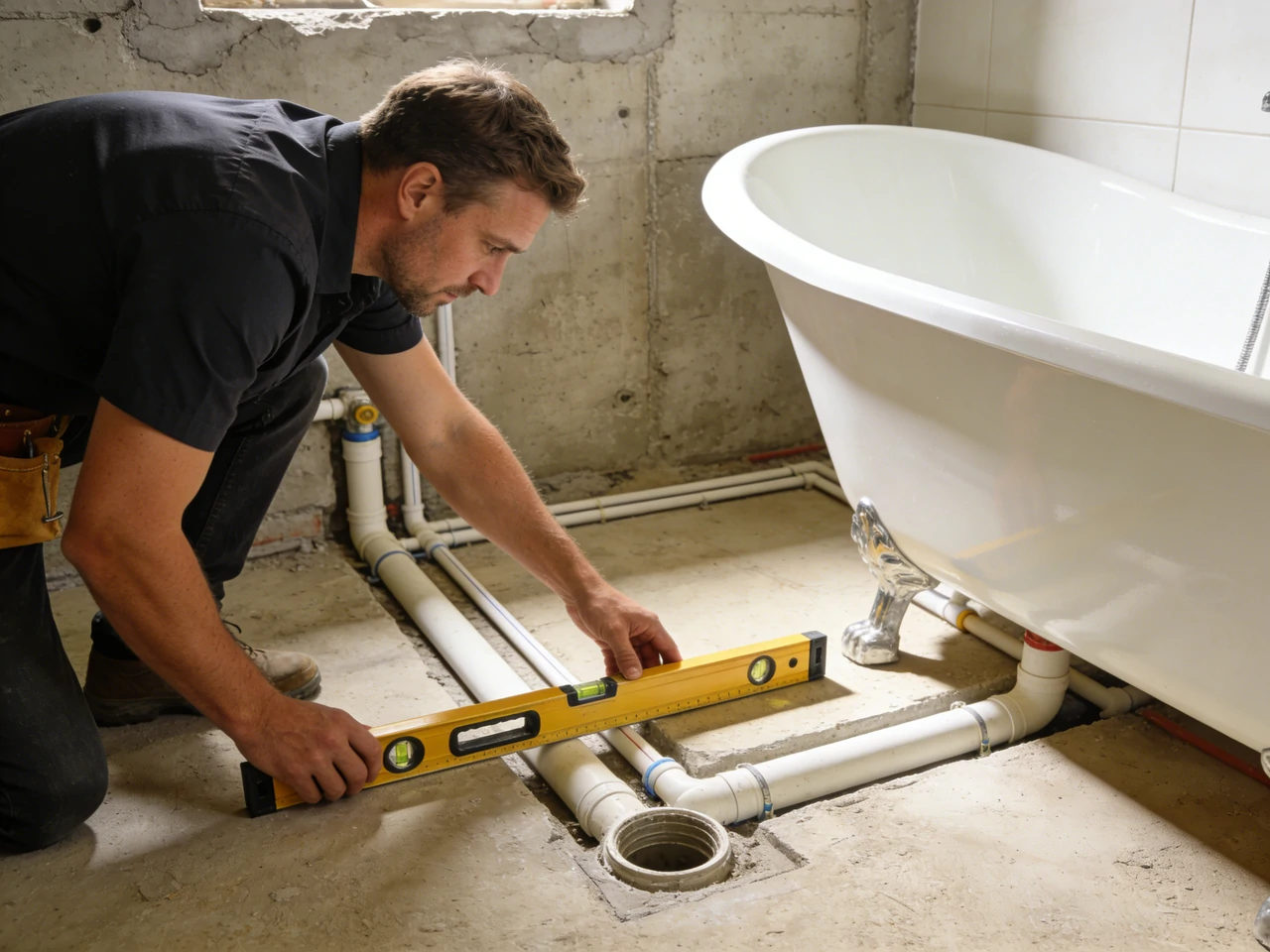
Drainage coordination is the most common cause of rework when you install freestanding bath units. The project objective is to ensure that the waste/overflow assembly, drain tailpiece, and plumbing trap interface can be connected within tolerance without imposing stress on the tub outlet or leaving inaccessible joints.
Standard drain compatibility: 1-1/2 inch drain systems, tailpiece length, and trap adapter interfaces
Many freestanding bath drain outlets are designed around 1-1/2 inch drain systems. For specification and procurement:
- Confirm the outlet thread/connection standard on the tub side.
- Confirm tailpiece length range and whether field cutting is permissible.
- Confirm trap adapter compatibility and the allowable angular misalignment before a flexible joint is required (where permitted by code).
Avoid assuming that any drain kit will match any tub. Treat the drain kit as a controlled accessory with defined tolerances and materials.
Waste-and-overflow assembly options (brass vs PVC/ABS): performance, code acceptance, and lifecycle trade-offs
Waste/overflow assemblies are selected based on durability, code acceptance, and maintenance strategy:
- Metallic assemblies (e.g., brass-based): typically higher mechanical robustness and better resistance to deformation during tightening; often preferred for long service life and repeated maintenance access.
- Thermoplastic assemblies (PVC/ABS where permitted): can reduce material cost and corrosion concerns but may be more sensitive to over-tightening and heat exposure depending on system design.
Specify compatibility with local plumbing code requirements and ensure that gasket materials are suitable for the temperature range and cleaning regime expected.
Rough-in location control: drain centerline tolerances, offset allowances, and set-out verification (diagram suggestion: plan + section)
Set-out control should be handled with a plan and section drawing that defines:
- Drain centerline coordinates from finished walls or control lines
- Vertical relationship of finished floor to trap inlet elevation
- Maximum allowable offset between tub drain outlet and floor drain line (as defined by the drain kit geometry)
- Box-out dimensions if a recessed trap zone is required
On projects, a controlled pre-pour verification (for slab) or pre-close verification (for framed floors) reduces late-stage conflicts that otherwise result in visible tub relocation or filler misalignment.
What rough-in dimensions are required for a freestanding bath drain?
The required rough-in dimensions are product-dependent and must be taken from the approved cut sheet and rough-in drawing. At specification level, procurement should require the supplier to state: (1) drain outlet centerline relative to tub footprint datum points, (2) acceptable tolerance window for the floor drain location (commonly expressed as ± mm/in), and (3) required vertical clearance for trap and tailpiece engagement. Without these three items, drain rough-in becomes a site assumption and increases the risk of misalignment and leaks.
Water supply and filler system integration
Water supply and filler selection is a coordination decision affecting rough-in complexity, waterproofing penetrations, and commissioning scope when you install freestanding bath units. The "freestanding’ form factor often leads teams to default to a floor-mounted tub filler; however, wall-mounted solutions can reduce underfloor complexity when architecture permits.
Floor-mounted tub filler coordination: supply routing, anchorage, and access for valve/service
For a floor-mounted tub filler:
- Confirm routing for hot and cold water supply lines without clashing with the drain line and trap.
- Provide a structural anchorage zone within the floor build-up; inadequate anchorage leads to movement at the spout and stress at fittings.
- Define a service strategy for the valve and connections (below-floor access or a planned access point), consistent with the project’s maintenance model.
Where coordination is poor, the filler becomes the critical path item that drives floor opening, patching, and schedule impacts.
Wall-mounted fillers and hand shower kits: backer requirements, waterproofing penetrations, and reach geometry
Wall-mounted fillers reduce floor penetrations but require:
- Backing/support in the wall to resist operational loads
- Waterproofing detailing at penetrations in wet zones
- Verified spout reach geometry relative to tub rim width and overflow location to prevent water striking the rim or deck area
Hand shower kits add functional requirements (hose routing, bracket positioning) and should be reviewed for compatibility with splash control and cleaning protocols in commercial settings.
Temperature/flow performance targets and scald protection requirements (Reference: ASSE/ASME; local code)
For project specifications, define:
- Minimum flow performance needed to meet operational turnover (fill time targets), accounting for building pressure losses
- Temperature control and anti-scald requirements aligned with applicable ASSE/ASME standards and local code
- Commissioning requirements for maximum outlet temperature settings where mandated
These requirements should be aligned with the building’s domestic hot water strategy and any central mixing provisions.
Which supply configuration reduces coordination risk in multi-unit projects?
Wall-mounted supply configurations often reduce coordination risk when the structure or slab limits underfloor routing, because they shift most tolerances into the wall rough-in zone with clearer access during construction. Floor-mounted tub fillers can be executed reliably in repeat units, but only when the project has standardized slab box-outs or consistent underfloor service zones and a defined access strategy for future service. The lowest-risk option is the one that matches the building’s repeatable rough-in capability and inspection access model.
install freestanding bath: acceptance criteria, sealing, and commissioning
Acceptance criteria should be written into the inspection and test plan so that trades and inspectors are aligned on measurable outcomes. This is the practical boundary between “installed” and “commissioned.”
Level and plumb acceptance: verification points, allowable deviation, and drainage performance criteria
Typical acceptance checks include:
- Level confirmation at multiple rim points and across the base footprint
- No rocking under load (dry load check and functional check under filled condition where permitted)
- Drainage performance: no standing water outside the designed residual film; no gurgling that indicates venting or trap issues
- No visible stress at the waste/overflow interface after tightening (misalignment indicates rough-in error)
Where teams search for “freestanding tub installation” guidance, projects should instead enforce these measurable outcomes as hold points before finishes are signed off.
Sealant specification and interfaces: silicone type, bead location intent, cure-time constraints (spec table suggestion)
Sealant is not always intended to “glue down” a freestanding tub; in many specifications it is intended as a hygiene and water-management interface to prevent moisture migration underneath the tub and to reduce cleaning ingress. The intent should be stated explicitly.
| Sealant Attribute |
Specification Target |
Notes |
| Chemistry |
Neutral-cure silicone or equivalent compatible elastomer |
Avoid formulations that can attack certain polymers/metals |
| Standard reference |
ASTM C920 (where applicable) |
Select appropriate class and grade for wet areas |
| Placement intent |
Perimeter bead as detailed; avoid blocking drainage paths where design requires |
Define whether full perimeter is sealed or strategic beads only |
| Cure constraints |
Protect from water exposure until cured per manufacturer data |
Coordinate with commissioning schedule |
Leak-testing and handover documentation: fill-to-overflow test, underside inspection access, and punchlist evidence
Leak-testing is a commissioning requirement, not an informal site check. A practical project protocol includes:
- Fill-to-overflow test to verify waste/overflow sealing under maximum head condition
- Timed drain test to observe joint behavior during discharge
- Underside inspection access (below-floor access, access panel, or documented pre-close inspection) to visually verify that no seepage occurs underneath the tub
- Photo documentation of connections prior to concealment, including trap alignment and gasket seating
This evidence reduces disputes during handover and provides a baseline if leaks are reported later.
What leak-testing protocol is required for project handover?
Handover leak-testing should be defined in the inspection and test plan and typically includes a fill-to-overflow hold period, followed by a full drain-down while observing all accessible joints, and a final check after a short interval to confirm no delayed seepage. If underside access is not available after closure, require a documented inspection before concealment, with sign-off by the responsible trade and the commissioning representative.
Codes, standards, and certification checkpoints
Codes and certifications determine what can be legally installed, including how to install freestanding bath units, and how they must be inspected. Procurement should screen compliance early to prevent substitutions that fail inspection or require redesign.
Plumbing code alignment and inspection dependencies (Reference: IPC/UPC; local AHJ requirements)
Confirm at specification stage:
- Applicable plumbing code pathway (IPC or UPC, or local equivalent)
- Inspection points: rough-in inspection before concealment, final inspection after commissioning
- Requirements for trap configuration, venting, and allowable fittings for the tub drain line
- Any restrictions on flexible connections or concealed joints
The authority having jurisdiction (AHJ) interpretation can affect whether certain access strategies are acceptable.
Material safety and performance references (Reference: ASTM material test methods where applicable)
Material selection (acrylic, solid surface, enameled metal, engineered composites) should be supported by relevant test references where applicable, such as:
- Surface performance and durability test methods
- Thermal cycling or impact-related references relevant to the material category
- Chemical resistance considerations tied to facility cleaning protocols
Where compliance requires third-party certification, ensure certificates match the exact model and production location.
Electrical requirements for jetted/air systems (Reference: UL; local electrical code coordination)
If the freestanding bathtub includes powered features (air or jet systems), coordinate:
- Electrical supply location and protection requirements (e.g., ground-fault protection where required)
- Access to service components without destructive removal
- Separation of wet-zone penetrations and cable routing
Electrical coordination should be treated as part of the bathroom product system, not an add-on.
Accessibility and project requirements screening (Reference: ADA where applicable; jurisdictional policies)
Freestanding baths are not inherently accessibility-compliant. For projects subject to accessibility requirements, screen:
- Clearance zones and approach requirements around the tub
- Controls reach ranges for fillers and hand showers
- Slip resistance expectations for surrounding floor finishes
If a freestanding bath is included for design intent, ensure it does not conflict with required accessible bathroom counts or layouts.
Manufacturing quality, sourcing, and multi-unit execution
For professional buyers and specifiers, consistency across units matters as much as single-unit aesthetics. Installation labor variability increases when dimensional tolerances and accessory compatibility are inconsistent.
Dimensional tolerances affecting install fit (rim geometry, drain set-out, foot adjustment range) (comparison matrix suggestion)
The following dimensional attributes most directly affect install outcomes:
| Attribute |
Why It Matters on Site |
What to Request in Submittals |
| Drain set-out accuracy |
Determines whether the tailpiece aligns without stress |
Stated tolerance window and datum references |
| Rim and base geometry consistency |
Affects perceived level and perimeter seal uniformity |
Critical dimensions with allowable deviation |
| Foot adjustment range (if applicable) |
Determines ability to compensate for floor variation |
Min/max adjustment and locking method |
| Base footprint definition |
Drives finish set-out, waterproofing detailing |
Footprint drawing and bearing zones |
When comparing suppliers for multi-unit procurement, request evidence that these tolerances are controlled in production and checked in QA.
Factory QA and shipment readiness: surface inspection, hydrostatic/leak checks, packaging for damage prevention
Quality planning should address:
- Surface inspection under controlled lighting to identify finish defects before shipment
- Leak checks or hydrostatic verification for integrated waste/overflow components where supplied as an assembly
- Packaging designed to prevent rim distortion and surface abrasion in transit and on-site staging
- Clear labeling of batch/lot identifiers to support repeatability and warranty traceability
This reduces site rejections that disrupt installation sequencing and trade availability.
Spares and service strategy for commercial turnover: drain components, leveling feet, and finish repair protocols
Commercial operators prioritize downtime reduction. A practical spares strategy includes:
- Replaceable drain components (gaskets, pop-up mechanisms where applicable)
- Spare leveling feet or adjustment hardware for footed systems
- Approved finish repair protocols for minor site damage, aligned with the material type and warranty conditions
Define which parts are standard across the product range to simplify inventory for distributors and facility operators.
Documentation and logistics for repeatable installs: batch consistency, labeling, and on-site verification checklist (structured template suggestion)
Repeatability improves when each delivery includes:
- Consistent revision-controlled documentation (cut sheets, rough-in drawings, accessory lists)
- Unit labeling that maps to drawings and inspection records
- An on-site verification checklist covering: drain location confirmation, filler rough-in confirmation, floor tolerance verification, and commissioning evidence capture
This approach reduces the variance in “install a freestanding tub” outcomes across floors, blocks, or phases.
Commercial cost and risk considerations (project framing)
Installation effort is driven by coordination complexity rather than the tub alone. When teams ask “Is it easy to install a freestanding bath?” the project answer is: it is predictable when rough-in access, drain set-out tolerances, and filler strategy are standardized; it is high-risk when slab constraints and late design changes force field adaptations.
“What to put under a freestanding tub?” should be treated as a specification decision: the under-base interface must support load without trapping moisture or damaging the finish. Depending on base type and acoustic requirements, this may involve a controlled bearing interface, a defined sealant strategy, and verified floor flatness—rather than ad hoc pads that compromise stability.
For “How much does it cost to install a free standing bath?” and “What’s the average labor cost to install a bathtub?” cost should be estimated using drivers and allowances rather than a single number:
- Labor hours increase with slab-on-grade trenching/box-outs, floor-mounted filler routing, and restricted access for leak inspection.
- Rework risk increases when drain location control is weak or when the selected waste/overflow kit is not matched to the tub outlet geometry.
- Commissioning and documentation requirements add time in commercial handover but reduce call-backs.
Procurement can reduce installed cost variability by specifying: verified rough-in drawings with tolerances, an agreed access strategy, compatible drain kits, and defined acceptance tests. The common downsides of a free standing bath in commercial execution are not functional; they are coordination-related—service access constraints, visible alignment issues if set-out is wrong, and higher exposure to finish damage during construction due to the exposed form factor.
FAQs
How to secure free standing tub in commercial projects without visible fixings?
Securing a freestanding tub in a commercial bathroom is about creating controlled load paths through the feet or plinth and making sure the tub is level. Start by checking that your bathroom floor is completely flat, and lift the tub carefully into position. Space around the tub should be enough to allow adjustments and prevent rocking. Apply a bead of caulk around the bottom edge to prevent water from seeping underneath the tub, but don’t rely solely on it—structural support and proper leveling are key. Following these expert tips ensures your new tub stays secure and transforms your bathroom with a clean, freestanding look.
What plumbing for freestanding tub should be specified to reduce rework?
When installing your freestanding tub, plan the plumbing connections carefully. Use a compatible drain tailpiece and plumbing trap, and ensure hot and cold water lines align with freestanding
faucets. Check that the tub’s drain sits at the correct height, and confirm that the floor is level so the tub may drain correctly. If your floor is uneven, adjust the feet or plinth to lower the tub safely. A plumber should verify pipe alignment before you install the drain. Proper planning avoids leaks and ensures the perfect tub installation process, keeping water from seeping underneath the tub and protecting finishes.
Can we finalize tile and waterproofing before freestanding tub installation?
Yes, but only if the bathroom floor is level to check tolerances and the plumbing rough-ins are in place. Clean the floor and make sure the surface is completely dry before placing the tub. Plan for the tub to sit so you can install freestanding faucets and complete the plumbing connections. Caulk around the bottom edge of the tub after positioning, then allow the caulk to dry before using. Following the installation guide from your tub manufacturer ensures the tub may be filled safely. This step guarantees that water won’t seep underneath the tub and sets you up for a smooth installation process.
What are the key acceptance criteria for freestanding tub installation at handover?
When installing the tub, verify that the tub is level and that it does not rock when lightly pushed. Test for leaks by filling the tub and inspecting the tub’s drain and drain tailpiece connections. Ensure your plumbing trap is secure and all freestanding faucets function properly. Check that water isn’t seeping underneath the tub and that there is adequate space around the tub for cleaning and maintenance. Follow expert tips from the tub manufacturer, and caulk around the bottom edge if needed, allowing it to dry. A new tub installed correctly will provide a luxury hot tub experience and transform your bathroom.
How should procurement evaluate multi-unit consistency for freestanding bathtubs?
For multi-unit projects, consistency is everything. Ensure all tubs from the tub manufacturer have the same base geometry and drain alignment, and provide dimensional checks for each unit. Verify that the floor is even where each tub will sit, and confirm that hot and cold water lines are positioned for each freestanding faucet. The plumber should test the plumbing connections and fill the tub to ensure no water is seeping underneath. Following an installation guide for installing your freestanding tub helps reduce labor variance, ensures every tub is level, and maintains uniform quality across multiple bathrooms, giving a predictable, perfect tub experience.
References