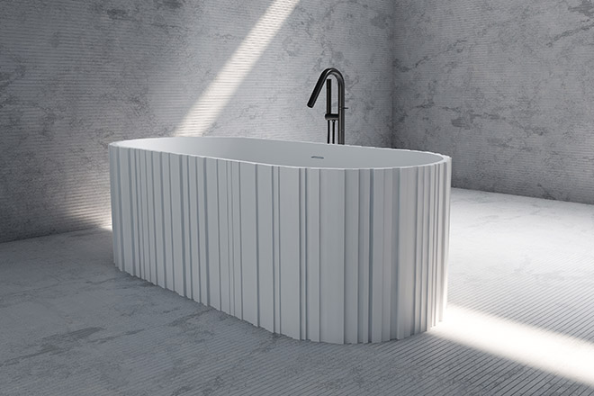
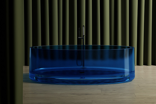
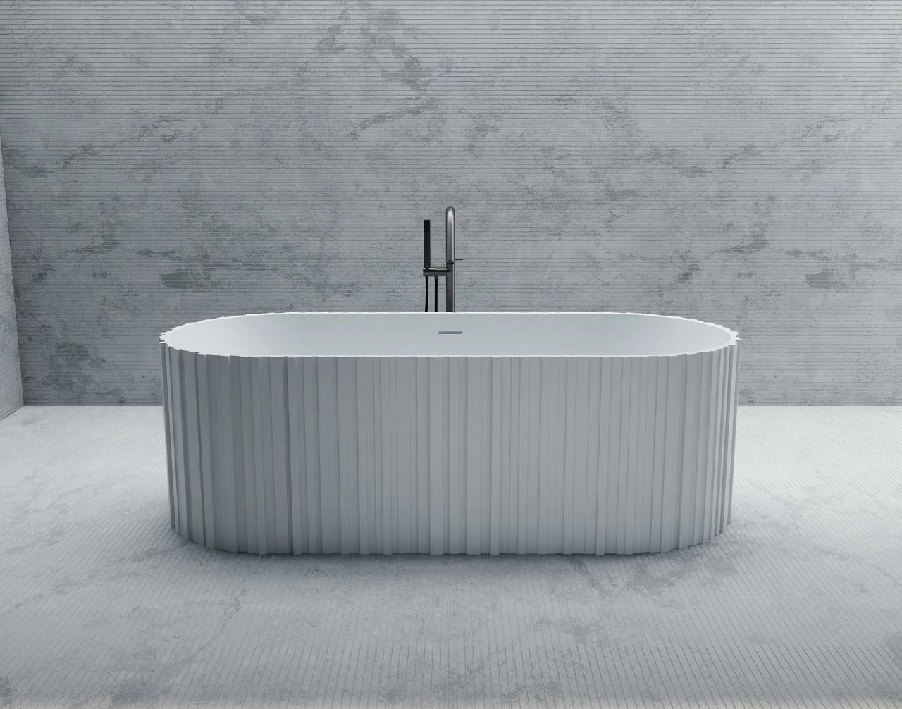
When freestanding bathtubs move from concept images into project delivery, dimensions become a coordination tool rather than a simple product attribute. In a specification context, freestanding tub dimensions define how the tub interfaces with structure, waterproofing, drainage, finishes, and service access across multiple units. Establishing dimensional intent early helps align design assumptions with procurement reality, reducing downstream conflicts during rough-in, installation, and inspection.
Scope for project specification and procurement
Freestanding bathtubs are typically specified as part of a complete wet-area system that includes waterproofing, floor and wall finishes, drain and overflow assemblies, trap access strategy, and a compatible tub filler (floor-mounted or wall-mounted). For project work, “freestanding tub dimensions” must be treated as a controlled set of submittal parameters rather than a single length × width label, because small variances can affect rough-ins, finish datums, and inspection access across multiple units.
Dimension parameters used in submittals (L × W × H, soaking depth, rim height)
Project submittals should distinguish between overall external dimensions and functional internal dimensions:
- Overall length (L): maximum exterior length at the rim line or widest point, depending on profile.
- Overall width (W): maximum exterior width at the rim line or widest point.
- Overall height (H): finished floor to top of rim.
- Rim height at entry side: relevant where designers require a consistent datum against adjacent flooring or a platform.
- Soaking depth (usable water depth): vertical distance from tub floor (or lowest point of the bathing well) to overflow weir elevation; this is more predictive than overall height.
- Overflow-to-rim distance: affects perceived “deep soak” while also bounding maximum waterline for compliance and safety.
- Base footprint: contact patch or support frame dimensions; used for floor flatness tolerance, leveling strategy, and point load review.
- Drain location: center, end, or offset measured from reference edges; used for rough-in coordination.
Fit-for-space vs fit-for-user: defining the decision criteria for projects
In multi-unit and hospitality programs,
tub selection commonly starts with fit-for-space constraints (bathroom plan module, doorway logistics, service access) and then proceeds to fit-for-user requirements (bathing well length, backrest geometry, soaking depth). A specification that prioritizes only external size often leads to late-stage changes when internal bathing length or overflow height fails to meet the program intent.
Data sources and verification hierarchy (ANSI, ASTM, ASME, IAPMO/UPC, ICC/IPC)
For procurement and risk control, dimensional values should be validated using a consistent hierarchy:
- Manufacturer-controlled drawings (dimensioned 2D + tolerance notes) and a controlled revision record.
- BIM/CAD objects that match published drawings and indicate reference planes for measurement.
- Third-party certification listings where the product standard includes dimensional requirements and conformity surveillance.
- Applicable plumbing codes governing waste/overflow and installation conditions (e.g., IPC/UPC adoption jurisdiction).
- Material and slip-resistance standards where referenced by the spec (e.g., slip testing methodology on bathing surfaces).
This hierarchy reduces field rework by aligning what is drawn, shipped, and inspected.
Freestanding tub dimensions: baseline ranges and categories
Across commercial supply chains,
freestanding tubs most commonly fall into 55–72 in length, 27–36 in width, and 18–30 in rim height. For schedules that target broad availability and predictable logistics, 60 × 30–32 × 20–24 in (L × W × H) is the most frequently repeated baseline.
Specification table: common dimensional ranges and “standard” sizes (imperial + metric)
| Size class (schedule use) |
Overall length |
Overall width |
Rim height (typical band) |
Metric equivalents (approx.) |
| Compact |
54–55 in |
27–28 in |
15–18 in |
1370–1400 × 685–710 × 380–460 mm |
| Standard |
59–66 in |
29–32 in |
18–24 in |
1500–1680 × 735–815 × 460–610 mm |
| Large |
70–72+ in |
32–36 in |
20–30 in |
1780–1830+ × 815–915 × 510–760 mm |
Common schedule anchor (availability-driven): 60 in length, 30–32 in width, 20–24 in rim height.
Size classes for schedules: compact, standard, large (length/width/height bands)
- Compact (≈54–55 in): used where plan modules are constrained, but requires careful review of internal bathing well length and service clearance because the same external length can yield different usable lengths depending on wall thickness and backrest angle.
- Standard (≈59–66 in): best for consistency across unit types; typically offers workable drain rough-in repeatability and fewer doorway/logistics constraints than 70–72 in units.
- Large (≈70–72+ in): requires early structural load review and receiving logistics planning; often selected to satisfy program requirements for deeper wells or dual-ended bathing, but increases water capacity and fill demand.
Plan/section diagram: key measurement points (overall length, max width, rim, overflow, base)
Dimension callouts in drawings should clearly identify measurement reference points:
- Plan view: overall length at rim, overall width at rim, base footprint outline, and drain centerline location from each end.
- Section view: finished floor to rim height, overflow weir elevation from finished floor, tub floor elevation, and base support method (integral feet, full perimeter base, frame, or pad points).
- Tolerance notes: identify which dimensions are critical to rough-in (drain centerline, overflow height, base footprint) versus nominal (rim contour).
What are the most common freestanding tub dimensions used in multi-unit schedules?
For repeat-unit procurement, the most common baseline used to balance availability, logistics, and bathroom module fit is 60 × 30–32 × 20–24 in (about 1525 × 760–815 × 510–610 mm). This size band typically supports consistent drain coordination and avoids the crating/turning constraints that frequently arise with 70–72 in tubs.
Space planning, clearances, and footprint coordination
Freestanding tubs introduce a perimeter condition on all sides, making freestanding tub dimensions a critical factor in space planning and coordination. Unlike alcove tubs, they require explicit clearance decisions for cleaning access, inspection, trap access strategy, and finish continuity at the wet-area boundary.
Minimum service clearances vs recommended access zones (spec notes for coordination)
A project specification should separate:
- Minimum service clearance: the space required to inspect key interfaces (overflow connection, waste connection, sealant joints where applicable, and floor penetrations). This is often driven by the selected access method (through ceiling below, adjacent access panel, or local removable trim).
- Recommended access zone: the space required for maintenance workflows and unit turnover without removing fixed finishes.
Where project geometry is tight, define at least one accessible side and one service strategy (e.g., below-ceiling access) in the coordination set rather than relying on field improvisation.
Footprint and door-path constraints: crating dimensions, turning radii, staging allowances
Procurement teams should request and review:
- Crated dimensions and gross weight, not only product dimensions. Crates can add meaningful width/length and change turning feasibility in corridors and elevators.
- Handling method assumptions (pallet jack vs. dollies vs. lift equipment) to confirm corridor widths and elevator car depth.
- Staging allowances for floor protection and temporary storage; freestanding tubs often arrive earlier than final finishes and must be protected from impact damage.
Door-path planning should use the crated envelope as the governing dimension unless the receiving plan explicitly permits uncrating at dock and protected transport to the unit.
Multi-trade interfaces: tile datum lines, base trim, and wet-area transitions
Key interfaces that should be shown in coordination drawings:
- Finish floor build-up at tub location (membrane, mortar, tile/stone) to ensure rim height and filler spout reach remain compliant after finishes.
- Wet-area boundary and water containment strategy (floor slope requirements, linear drain positioning where used, and transition details to dry zones).
- Base trim and shadow gaps: if the tub is set near walls, define tolerance zones to avoid visibly uneven gaps caused by wall out-of-plumb or tile thickness variation.
What clearance should be specified around a freestanding tub for inspection and service access?
Where program area permits, many commercial specs target a recommended access band of roughly 30–36 in (760–915 mm) on at least one working side to support inspection and service without finish removal. If the plan cannot support that, the specification should require an alternative service route (for example, trap access from below or an adjacent access panel) and identify the governing dimensions and access opening requirements in the architectural and plumbing sets.
Ergonomics and functional depth: soak performance tied to dimensions
Professional selection should prioritize usable water depth to overflow and internal bathing well length rather than relying on overall rim height or nominal length.
Soaking depth vs overall height: how to specify usable water depth and overflow elevation
A tall rim does not guarantee a deep soak if the overflow is positioned high relative to the rim or if the internal floor is raised by reinforcement or base geometry. For controlled outcomes, submittals should state:
- Overflow elevation from finished floor
- Tub floor elevation from finished floor
- Usable soaking depth = overflow elevation − tub floor elevation
This approach is also easier to coordinate with filler spout placement and splash control in compact bathrooms.
Water capacity bands by size class (gallons/liters) for hot-water system planning
Water capacity should be specified as a tested fill volume to overflow (not marketing volume). Typical planning bands:
| Size class |
Typical fill to overflow |
Hot-water system implications (planning-level) |
| Compact |
~40–55 gal (150–210 L) |
Often compatible with standard domestic hot-water recovery, but confirm peak demand profile in hospitality |
| Standard |
~50–70 gal (190–265 L) |
May require demand review when multiple tubs can fill concurrently on a riser |
| Large |
~70–90+ gal (265–340+ L) |
Higher risk of concurrent peak loads; verify recovery, storage, and recirculation balancing |
For engineering review, convert volume to weight using 8.34 lb/gal (≈1.0 kg/L) and add dry tub weight and occupant load for structural and vibration checks.
Single-user vs dual-ended bathing wells: internal length and backrest geometry implications
- Single-ended wells commonly prioritize one recline zone; internal length is governed by the backrest angle and the location of the drain/overflow end.
- Dual-ended wells (often with center drain) allocate two recline zones; they can require more overall length to preserve usable internal length at both ends, and they tighten drain rough-in tolerance expectations because the drain is visually centered in the room.
From a specification standpoint, request internal bathing well length at overflow height (or at a defined waterline) when user comfort is a program requirement, because interior contours vary significantly at the same nominal external length.
Which dimension best predicts soak comfort in hospitality or residential developments—length, width, or depth?
For predictable outcomes across a program, usable soaking depth to the overflow is typically the best single predictor because it controls the achievable waterline independent of rim styling. Internal bathing well length is the next most predictive when tall occupants or dual-ended use cases are defined in the brief. Overall width is usually a secondary factor unless accessibility clearances, transfer conditions, or a specific fixture envelope is required.
Drain location, rough-ins, and system compatibility
Drain and overflow coordination is where dimensional control most directly affects field labor and rework risk, particularly in repeat-unit construction.
Drain placement taxonomy: center, end, offset—impacts on rough-in tolerances and layout
- Center drain: common where symmetry is required; places higher emphasis on accurate centerlines and consistent tub positioning.
- End drain: can simplify alignment with a wet wall, but may constrain backrest geometry and internal well layout.
- Offset drain: used to balance user ergonomics with site plumbing constraints; requires careful shop drawing review to avoid clashes with joists, post-tension zones, or slab penetrations.
Drain placement should always be dimensioned from two orthogonal references (e.g., tub end and tub side) to avoid cumulative layout error.
Rough-in coordination: waste outlet, trap access, and floor penetration zones (IPC/UPC via ICC/IAPMO)
At planning level, coordinate:
- Waste outlet location relative to structural framing and slab penetrations
- Trap access method (from below, from adjacent room, or from an access panel) to satisfy inspection and maintenance requirements in the adopted code environment
- Overflow connection path and space claim within the tub body
The adopted IPC or UPC and local amendments govern minimum requirements; procurement should verify that product documentation supports compliance submittals in the project jurisdiction.
Faucet strategy constraints: floor-mounted vs wall-mounted spouts (reach, rim height, deck clearance)
Tub dimensions interact directly with filler selection:
- Floor-mounted spouts require defined spout reach to the basin, valve location clearance from the tub body, and coordination with finished floor build-up.
- Wall-mounted spouts require a controlled distance from the wall to the tub rim and a defined spout projection to avoid splash and to meet fill performance targets.
For either strategy, specify the rim height and the rim-to-waterline relationship (overflow elevation) so the spout height and arc are appropriate and consistent across units.
What drain rough-in tolerances should be held to avoid field rework across multiple units?
For repeatability, hold the drain rough-in centerline to a project-controlled tolerance that aligns with the tub’s actual connection geometry and the chosen waste/overflow assembly. A common commercial approach is to target ±10 mm (±3/8 in) on the drain centerline in both axes, provided the tub’s outlet and connector system can accommodate that range without forcing the body out of position. The correct tolerance must be confirmed against the tub’s published connection offset limits and the approved waste/overflow assembly.
Material and construction effects on dimensional stability
Material selection affects dimensional stability, surface durability, shipping risk, and consistency across production lots—all of which influence how reliably published freestanding tub measurements hold in the field.
Material comparison matrix: acrylic, enameled steel, cast iron, solid surface/stone resin—dimensional outcomes
| Material system |
Dimensional behavior (project-relevant) |
Typical procurement considerations |
| Acrylic (often reinforced) |
Can exhibit higher thermal expansion and potential deflection if base support is inadequate; consistency depends on tooling control and reinforcement method |
Lower shipping weight; verify base design to prevent rocking and to control rim levelness |
| Enameled steel |
Generally stable geometry; enamel layer requires impact protection during handling to avoid edge chipping |
Moderate weight; good repeatability; check chip resistance and repair policy |
| Cast iron (enameled) |
High rigidity and dimensional stability; heavy mass can reduce movement |
High shipping weight and handling constraints; structural load review is more likely to govern |
| Solid surface / stone resin |
Typically stable with controlled casting; edges and rim profiles can be tightly controlled if molds are maintained |
Weight between acrylic and cast iron depending on formulation; verify color stability and repairability requirements |
Thermal expansion, deflection, and base support: when nominal dimensions deviate in service
Two project conditions commonly cause “dimension drift” relative to submittals:
- Thermal expansion from hot water: materials expand differently and can change the perceived gap at walls or trims if the layout assumes a constant perimeter joint.
- Base support and floor flatness: if the base contacts the floor at limited points, small substrate deviations can cause rocking or rim out-of-level, which then affects filler alignment and visible joint lines.
To control these risks, specify base support expectations (full-contact, frame, or feet) and require floor flatness/levelness assumptions to be stated in coordination notes.
Surface thickness and reinforcement schemes: impact on rim width, overflow geometry, and perceived height
Wall thickness and reinforcement influence:
- Rim width (filler splash behavior and cleaning access)
- Overflow cover fit and overflow channel geometry
- Internal bathing volume at a fixed external envelope
When comparing alternates, require confirmation that the overflow elevation and internal well dimensions remain equivalent, not only the outside length and width.
Compliance references for material systems (ANSI Z124 / CSA / ASTM, as applicable by material)
Depending on material and certification route, bathing fixtures may be evaluated to ANSI Z124 (commonly referenced for plastic plumbing fixtures) and/or relevant ASME/CSA fixture standards used in North American conformity assessment. Slip-resistance test methods may be referenced where required by the spec (e.g.,
ASTM F462 for bathing surfaces), subject to jurisdictional acceptance and the project’s risk framework.
Structural loading and building interface requirements
Freestanding tubs concentrate load over a smaller footprint than alcove tubs, and that load changes significantly when filled.
Loaded weight model: dry weight + water + occupant(s) for structural review (psf and point loads)
For structural review, use a conservative model:
- Total load = dry tub weight + water weight to overflow + occupant allowance
- Water weight: 8.34 lb/gal (or 1 kg/L)
Example planning check (standard size band):
- Fill volume 60 gal → ~500 lb water
- Add tub dry weight (varies by material)
- Add occupant allowance (project-defined)
- Distribute over the actual base footprint, not the overall rim footprint
This model supports both psf review and localized point load checks where the base contacts the floor at discrete points.
Floor leveling and substrate flatness tolerances: base contact requirements and rocking risk
Specifications should state substrate tolerance expectations (flatness and levelness) consistent with the base design. If the tub relies on a small set of feet or pads, tighter substrate control is typically required to prevent rocking and to keep the rim level. If the tub uses a full-contact base or frame, it may be more forgiving but can increase sensitivity to finished floor build-up variation.
Seismic and movement allowances: anchoring approaches and slip-resistance considerations (ASTM F462 for slip)
Where seismic design categories or building movement are concerns, define whether the tub is:
- Set in place with movement allowance (and controlled interface joints), or
- Mechanically restrained per the project’s structural and code requirements
If slip performance is specified for bathing surfaces, align requirements to a recognized test method and acceptance approach (noting that slip criteria can be jurisdiction-specific). Where cited, ASTM F462 is commonly referenced as a testing standard for bathing surfaces.
Documentation for permit and engineering review: what to include in submittal packages
A permit-ready submittal set typically includes:
- Dimensioned drawings with critical rough-in dimensions and tolerances
- Product mass (dry) and stated fill volume to overflow
- Material description and conformity documentation (where applicable)
- Installation requirement notes at a coordination level (access strategy, service clearance assumptions)
- BIM/CAD objects aligned to the approved drawing revision
Manufacturing tolerances, quality control, and documentation deliverables
For project consistency, published freestanding tub measurements must be supported by defined tolerances and a quality system capable of controlling mold/tool wear, reinforcement variability, and finishing processes.
Dimensional tolerances and inspection points: rim-to-overflow, drain-to-wall, base footprint (ANSI/ASTM where applicable)
Procurement and design teams typically prioritize tolerance control on:
- Drain centerline position relative to tub ends/sides
- Overflow elevation relative to rim and finished floor reference
- Base footprint dimensions and flatness (stability on site)
- Rim levelness under defined support conditions
Where standards are applied as part of certification, confirm which dimensions are evaluated and how conformity is surveilled, then ensure the project’s critical dimensions are explicitly included in the manufacturer’s inspection plan.
Visual/structured elements: GD&T-style callouts, control plans, and first-article inspection records
For repeat-unit projects and distributor programs, request:
- Drawings with unambiguous reference planes and measurement points
- A control plan identifying critical-to-function and critical-to-appearance dimensions
- First-article inspection records for initial production lots (especially for custom colors, altered drain positions, or modified base supports)
These elements reduce schedule risk when alternates are proposed or when multiple production runs are required.
Certification and traceability: batch marking, QA records, and conformity declarations (ISO 9001 framework where used)
Traceability should support issue containment without broad unit replacement. Common controls include:
- Batch/serial marking linked to production date and tooling set
- Retained QA records for dimensional checks and surface inspection
- Conformity declarations aligned to the project’s specified standards and listing requirements
Where an ISO 9001 framework is used, confirm scope coverage (product line and site) and how nonconformities are handled for shipped goods.
BIM/CAD deliverables: 2D DWG + 3D/Revit families aligned to published dimensions
BIM/CAD objects should be treated as controlled submittals:
- Geometry must match the latest approved drawing revision
- Reference planes should be defined (finished floor, centerline, rim plane)
- Critical parameters (overall L/W/H, drain offsets, overflow elevation, base footprint) should be schedulable
Where models are “generic,” the drawings must govern; this hierarchy should be stated in the specification.
Sourcing and selection framework for commercial and project applications
A procurement-ready evaluation balances dimensional compliance, production capacity, and logistics risk against program constraints.
Bid comparison framework: dimension compliance, lead time, MOQ, and allowed alternates
A structured comparison typically includes:
- Dimensional compliance: match to schedule size class plus critical rough-in dimensions and tolerances
- Documentation completeness: drawings, tolerance notes, conformity documentation, and BIM/CAD availability
- Lead time and production scalability: ability to support phased deliveries and consistent tooling
- MOQ and finish options: whether project-specific finishes alter lead time or introduce batch variation risk
- Allowed alternates: rules for equivalency (internal well dimensions, overflow height, drain placement, base footprint)
Packaging and logistics constraints: crate size, freight class, damage-risk controls, receiving criteria
Receiving criteria should be written into the procurement package:
- Acceptable crate condition and labeling
- Inspection steps at receiving (external damage checks; do not rely on post-install discovery)
- Replacement part policy for overflow covers, feet, and trim components
- Requirements for corner/edge protection (especially for enameled surfaces)
Application mapping: hospitality, multi-family, healthcare, and high-rise—dimension-driven constraints
- Hospitality: repeatability and fast unit turnover make drain tolerance, surface repair policy, and access strategy critical; water capacity affects peak load engineering.
- Multi-family: doorway logistics, floor assemblies, and consistent rough-ins across stacked units typically govern; standard sizes reduce alternates.
- Healthcare and assisted living: freestanding tubs may be limited by accessibility requirements and cleaning protocols; if used, define clearances and transfer conditions explicitly and confirm compatibility with facility standards.
- High-rise: elevator and corridor constraints often eliminate large crated units; specify allowable crated envelope early and confirm staging plans.
Closeout requirements: as-built dimension verification, O&M submittals, and warranty documentation boundaries
Closeout packages typically include:
- As-built verification of drain rough-in location relative to installed tub position (sampling plan for multi-unit)
- O&M documentation covering approved cleaning chemistry ranges (generic, neutral-pH and non-abrasive guidance where applicable) and surface repair procedures
- Warranty boundaries tied to approved installation conditions (support, leveling, access strategy) and exclusion conditions (impact damage during handling)
FAQs
What is the standard size for a freestanding tub in project schedules?
In most projects, the standard freestanding tub sizes people rely on are fairly predictable. A common reference is around 60 inches in length, about 30–32 inches wide, and 20–24 inches in rim height. This freestanding bathtub size works well because it balances comfort with efficiency and fits many layouts without redesign. While stand alone tub sizes can vary, this range is considered a safe baseline when choosing tub size for soaking tubs in residential or hospitality settings. Designers still need to look beyond the bathtub size and confirm internal depth, gallons to overflow, and whether the tub is spacious enough to deliver a comfortable, immersive soak.
How much space is needed around a freestanding tub in a commercial bathroom layout?
Freestanding tubs usually need more breathing room than tubs built into walls. In commercial layouts, it’s common to plan 30–36 inches of space around the tub on at least one side. This space around the tub supports cleaning and accessibility, future maintenance, and drain and water access. In smaller bathrooms or where bathroom space is limited, that clearance may not be possible, so teams often define an alternate access strategy. Even in tight layouts, the goal is to keep the tub accessible and comfortable for the user while still allowing service work without removing finishes or disrupting surrounding areas.
Is a 59 inch freestanding tub too small for multi-unit developments?
A 59-inch model sits at the compact end of popular freestanding options, but it isn’t automatically too small. For projects with limited bathroom space, a small freestanding tub or smaller freestanding design can be the right freestanding tub size if internal proportions are well designed. The key is whether the tub allows space to stretch and supports a deep soaking tub experience. Some smaller tubs feel shallow due to backrest angle or wall thickness, while others still deliver a spa-like soak. Always review inches in length at the waterline, not just the outside dimensions, before selecting a bathtub.
Is a 1500 mm freestanding bath too small for international projects?
A 1500 mm tub, roughly equivalent to 59 inches, is generally considered a smaller option internationally, but it can still be a perfect freestanding solution for compact homes. In small bathrooms, homeowners often prioritize aesthetics and a sleek profile over sheer size. That said, the right size freestanding tub must still support how people actually use the tub—whether for a quick soak or a longer, spa-style experience. Procurement teams should also confirm the weight of the tub when filled, crated dimensions, and whether the tub will fit through doors and corridors during delivery.
What are the main downsides of specifying a freestanding bath in commercial projects?
While a freestanding tub is an excellent design feature, it comes with trade-offs. Freestanding tubs require more coordination than alcove or clawfoot styles, including careful planning for drain and water connections, floor flatness, and space around the tub. Large freestanding tubs and other large tubs can increase water gallon demand and structural load, especially when filled for a dream soak. They also introduce more exposed joints, which affects long-term maintenance. Still, when teams choose the right freestanding tub size and best material for freestanding tub use—such as high-quality acrylic or cast iron or stone—the result can feel immersive, durable, and visually striking.
References